


Spray Booth Airflow Calculation Explained

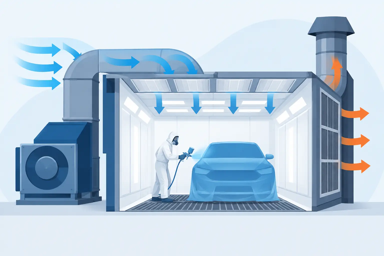
A spray booth can look substantial while still moving too little air where it matters. Poor capture at the operator’s position, paint mist escaping through doors, uneven finishes and filters blocking prematurely are usually signs that the system’s airflow has not been matched properly to the booth, process and ductwork. A correct spray booth airflow calculation provides the starting point for a safer, more controlled finishing area.
The calculation itself is straightforward. Selecting fans, filters and extraction equipment from that figure is where practical experience matters. Air volume must be sufficient to carry overspray away from the work, but the fan also has to overcome resistance from intake filters, extract filters, duct runs, bends, dampers and any heating or air replacement equipment.
What the airflow calculation is designed to establish
Airflow is normally expressed as cubic metres per second (m³/s), cubic metres per hour (m³/h) or litres per second (l/s). It describes the volume of air the system must move. Air velocity, normally expressed in metres per second (m/s), describes how quickly that air passes through a particular opening or booth section.
The basic calculation is:
Airflow volume (Q) = area (A) × air velocity (V)
For a cross-draught booth, the relevant area is usually the internal width multiplied by the internal height. Air enters at one end and travels horizontally towards the extraction end, so that vertical face is the area through which the airflow passes.
For a downdraught booth, air travels downwards from the ceiling plenum towards the extracted floor. The relevant area is generally the booth floor area, calculated from its internal length and width. A semi-downdraught design requires more care because the air is introduced and extracted through different sections, rather than uniformly across the full booth.
This is the theoretical airflow requirement. It should not be treated as the final fan specification.
A simple cross-draught example
Consider a booth with an internal width of 4 m and height of 2.5 m. Its airflow face area is 10 m². If the intended average air velocity through the booth is 0.4 m/s, the calculation is:
10 m² × 0.4 m/s = 4.0 m³/s
To express this as an hourly volume, multiply by 3,600:
4.0 m³/s × 3,600 = 14,400 m³/h
That figure indicates the air volume the system needs to move under the stated conditions. It does not mean that any fan advertised at 14,400 m³/h will be suitable. Fan performance falls as system resistance rises, and published fan duties need to be considered against the actual pressure the installation will create.
Choosing the right target air velocity
There is no sensible one-size-fits-all velocity for every spraying operation. The required value depends on the coating, application method, workpiece size, booth type and how operators use the space.
A small component booth spraying lower volumes of material will have different requirements from a vehicle refinishing booth, a joinery finishing room or a metal fabrication line coating large fabricated assemblies. Electrostatic application, high-output airless equipment and manually sprayed solvent-based products each create different overspray and vapour challenges.
Higher velocity can improve the direction of airflow and help contain overspray. However, excessive velocity can create turbulence, disturb the spray pattern, increase energy use and pull dust into the work area if the intake arrangement is poor. It can also increase noise and shorten filter life.
Lower velocity reduces fan energy and heating demand, but may allow paint mist to remain in the booth for longer or escape through access openings. The practical aim is stable, even airflow from clean air entry to extraction, with enough capture to control the process without creating unnecessary disturbance.
For this reason, target velocities should be set as part of the booth design and risk assessment, not copied from an unrelated installation. The coating supplier’s guidance, the equipment manufacturer’s recommendations, the booth design, relevant UK safety requirements and the insurer’s expectations may all affect the final specification.
The spray booth airflow calculation is only the first step
Once the required air volume is known, the next job is to establish the system resistance, commonly called total pressure or static pressure. This is the pressure the fan must overcome while delivering the required volume of air.
Resistance is created by every part of the system: inlet grilles, intake filters, ceiling plenums, extract filters, ductwork, bends, transition pieces, dampers, discharge stacks and heat recovery equipment where fitted. Long duct runs and sharp bends are particularly significant. A fan located close to a booth with a short, well-designed duct run will not perform in the same way as the same fan installed at the end of a lengthy, restrictive route.
Filter condition is equally important. New filters present a lower resistance than filters loaded with paint particulate. If the fan is selected only around clean-filter pressure, airflow can fall below the design duty well before the filters are visibly blocked. The design should account for the expected working pressure range and include suitable indication of filter loading, such as pressure gauges or differential pressure monitoring.
This is why fan selection should be based on a fan curve at the required air volume and total pressure, rather than a headline airflow figure. The motor, variable speed control, belt arrangement where applicable and available electrical supply also need to be suitable for that duty.
Booth layout changes the real-world result
Two booths with the same internal dimensions can perform very differently. Airflow distribution is affected by the design of the air inlet, plenum depth, diffuser arrangement, filter coverage, extraction pit or chamber, and the location of doors and personnel access.
A concentrated extract point can leave weak areas elsewhere in the booth. A poorly balanced ceiling plenum can produce fast and slow zones across the working area. Open personnel doors, vehicle access doors or oversized service penetrations can disrupt the designed air path and draw unfiltered air into the booth.
The size and shape of the workpiece matter too. A large cabinet, vehicle body or fabricated frame creates an obstruction in the airflow. Air has to travel around it, which can create recirculation zones behind the item. This does not automatically make the booth unsuitable, but it should be considered when deciding the booth dimensions, extraction arrangement and working method.
Where a booth forms part of a production line, material handling should be included early. Overhead tracks, rails, conveyors and loading doors all influence the available air paths. Retrofitting extraction after the layout is fixed can result in compromises that a planned system would avoid.
Make-up air, heating and building pressure
Extracting air from a booth means replacement air must enter the building or be supplied mechanically. If replacement air is not properly managed, the workshop can become excessively negative in pressure. Doors become difficult to open, cold air is pulled through gaps, dust is drawn in and the booth fan may not achieve its intended airflow.
A balanced spray booth system supplies filtered replacement air in a controlled way. Where heated air is required, the heater must be sized for the air volume, desired temperature rise and operating pattern. High airflow improves containment only if the resulting heating energy can be justified and the system can maintain workable conditions throughout the year.
For some industrial applications, a non-heated extraction arrangement may be appropriate. For refinishing and quality-sensitive work, controlled filtered supply air and drying capability are often more important. The correct approach depends on production volume, finish standard, building condition and operating costs, rather than the lowest initial equipment price.
Verify performance after installation
A calculation is a design tool, not proof of installed performance. Once commissioned, airflow should be measured and checked at representative points. This can identify uneven distribution, restrictive ductwork, incorrect fan rotation, leakage, filter issues or dampers that have not been set correctly.
Spray booth extraction is a form of local exhaust ventilation. Under UK COSHH requirements, LEV systems need suitable examination and testing at prescribed intervals, commonly at least every 14 months for many systems. Routine checks between formal examinations are still needed. Filter changes, pressure readings, visible airflow behaviour and operator reports all provide useful early warning that performance is changing.
Keep records of commissioning figures, fan settings, filter types and pressure readings. They give maintenance teams a baseline and make it easier to identify gradual loss of duty before it affects finish quality or exposure control.
Information needed for an accurate design
A meaningful proposal should start with more than the booth’s external dimensions. The key information includes the maximum workpiece size, coating type, application equipment, expected throughput, building layout, available power supply, proposed duct route and whether the process requires heating or bake cycles.
It is also useful to establish how the booth will actually be used. Will operators spray with vehicle doors open? Will parts enter on an overhead track? Is the booth used intermittently or across multiple shifts? Is there adequate space for a mixing room, preparation area and clean loading route? These details affect both airflow demand and the practicality of the finished installation.
At APEX Coating Systems, this is why booth airflow is considered alongside filtration, ducting, heating, access and production flow rather than as an isolated fan figure. A calculation is valuable when it leads to a system that performs consistently in the workshop, not simply on a drawing.
Before committing to a booth or extraction upgrade, measure the actual working space, define the largest and most demanding job, and assess the full air route from intake to discharge. That groundwork gives the airflow calculation a practical purpose: a safer spraying environment and a finish that is easier to produce consistently.
